 Video
Video PDF Download
 Contact us
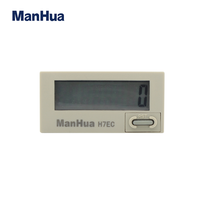
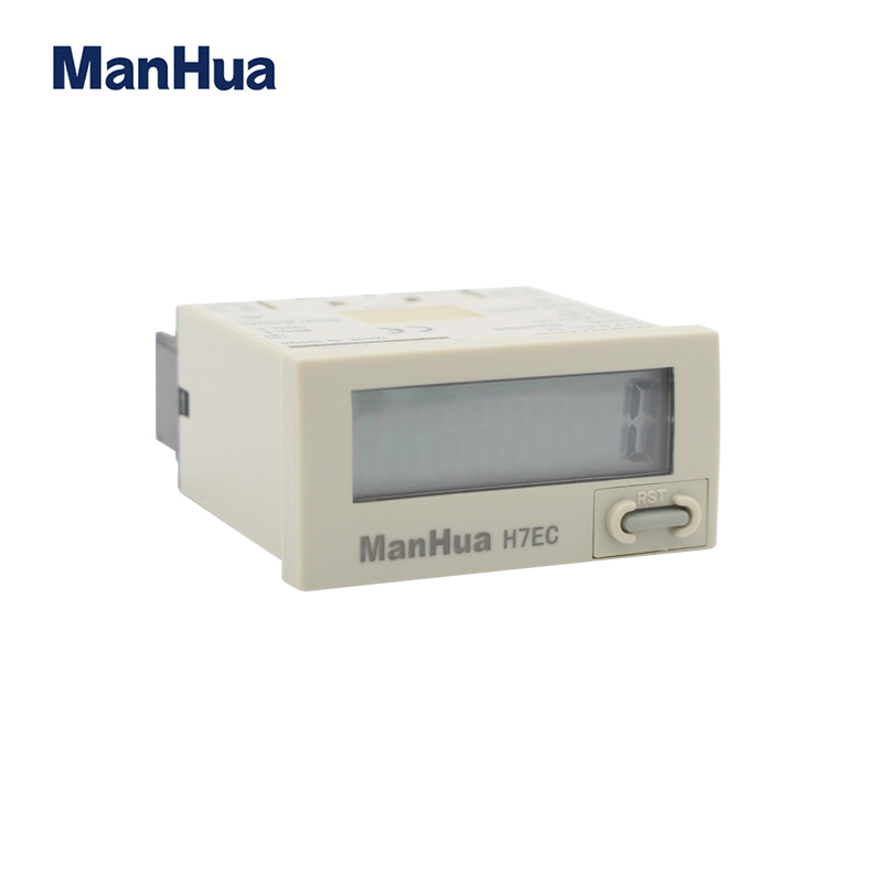
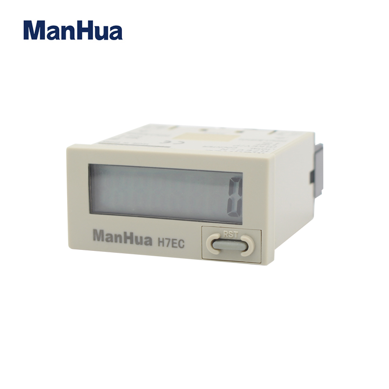
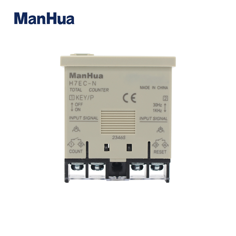
1. Large display with 8.6-mm character height.
2. Light-gray cases available
3. PNP/NPN universal DC voltage input types now available.
4. Battery is replaceable for Totalizer reuse and conservation of the environment.
5. Key-protect switch to prevent faulty reset key operation.
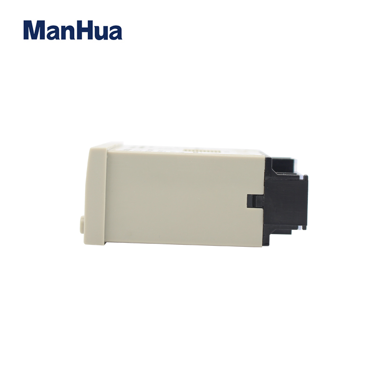
6. Short body, all models have a depth of 48.5 mm.
Conforms to EN60950-1 2006 A2 2013
Allowing use in residential, commercial and light- and heavy-industry environments.
Eight-digits, counting range 0 to 99999999
Model Number Structure
Model Number Legend
Note: Some configurations are not available.
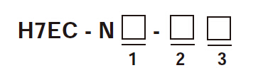
1. Count Input
None: No-voltage input
V: PNP/NPN universal DC voltage input
FV: AC/DC multi-voltage input
Specifications
General
|
Item |
H7EC-NV-@
H7EC-NV-@H
|
H7EC-NFV-@ |
H7EC-N-@ |
|
Operating mode |
Up type |
||
|
Mounting method |
Flush mounting |
||
|
External connections |
Screw terminals, optional Wire-wrap Terminals (see note 1) |
||
|
Reset |
External/Manual reset |
||
|
Number of digits |
8 | ||
|
Count input |
PNP/NPN universal DC voltage input |
AC/DC multi-voltage input |
No-voltage input |
|
Display |
7-segment LCD with or without backlight, zero suppression (character height: 8.6 mm) (see note 2) |
||
|
Max. counting speed |
30 Hz/1 kHz |
||
|
Case color |
Light gray |
||
|
Approved standard |
Conforms to EN61010-1/IEC61010-1 (Pollution degree2/overvoltage category III) |
||
Ratings
|
Item |
Item H7EC-NV-@
H7EC-NV-@H
|
H7EC-NFV-@ |
H7EC-N-@ |
|
Supply voltage |
Only for backlight
Powered by built-in battery
|
Not required (powered by built-in battery) |
|
|
Count input |
High (logic) level: 4.5 to 30 VDC
Low (logic) level: 0 to 2 VDC
(Input impedance: Approx. 4.7 kΩ)
|
High (logic) level: 24 to 240 VAC/VDC,
50/60 Hz
Low (logic) level: 0 to 2.4 VAC/VDC, 50/
60 Hz
|
No voltage input
Maximum short-circuit impedance:
10 kΩ max.
Short-circuit residual voltage: 0.5 V max.
Minimum open impedance: 750 kΩ min.
|
|
Reset input |
No voltage input
Maximum short-circuit impedance:
10 kΩ max.
Short-circuit residual voltage: 0.5 V max.
Minimum open impedance: 750 kΩ min.
|
||
|
Max. counting
speed (see note)
|
30 Hz or 1 KHz
(Switchable with switch)
|
||
|
Minimum signal
width
|
20 Hz: 25 ms
30 Hz: 16.7 ms
1 KHz: 0.5 ms
|
||
|
Reset system |
External reset and manual reset: Minimum signal width of 20 ms |
||
|
Terminal screw
tightening torque
|
0.98 N·m max. |
||
|
Ambient temperature |
Operating: –10°C to 55°C (with no condensation or icing)
Storage: –25°C to 65°C (with no condensation or icing)
|
||
|
Ambient humidity |
Operating 25% to 85% |
||
Connections
Terminal
Bottom view: View of the Total Counter rotated horizontally 180°
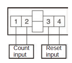
|
PNP/NPN Universal DC Voltage Input Model |
No-voltage Input Model |
|
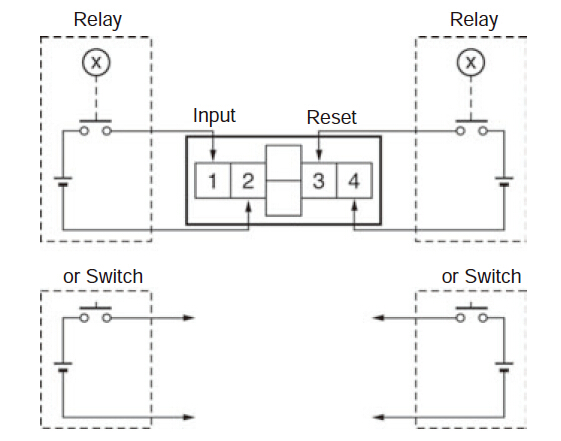
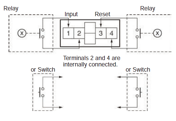
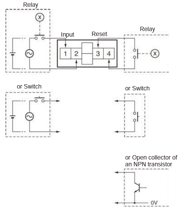
1. Contact Input (Input by a Relay or Switch Contact) |
1. Contact Input (Input by a Relay or Switch Contact) |
 |
 |
|
|
Note: Use Relays and Switches that have high contact reliability because the current flowing from terminals 1 or 3 is small. It is recommended that G3TA-IA/ID be used as the SSR. |
|
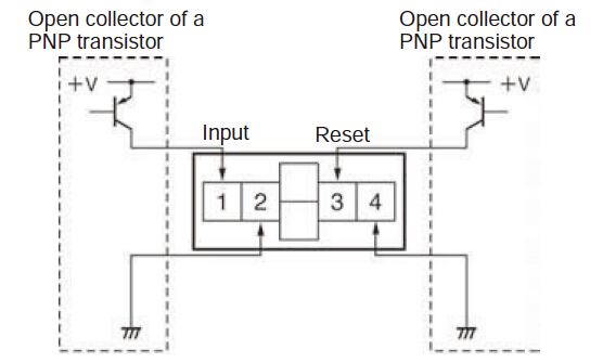
2. Solid-state Input |
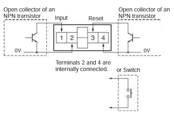
2. Solid-state Input (Open Collector Input of an NPN Transistor) |
 |
 |
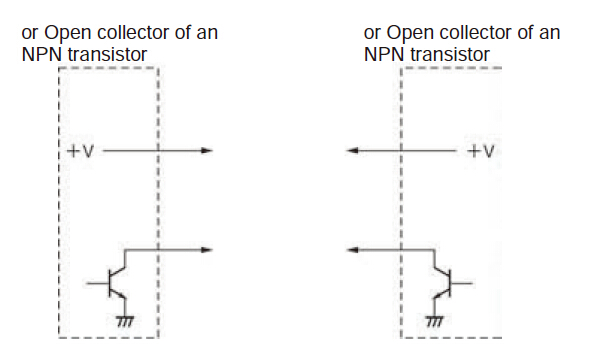 |
Note: 1. Residual voltage in the output section of Proximity Sensors or Photoelectric Sensors becomes less than0.5 V because the current flowing from terminals 1 or 3 is small thus allowing easy connection. 2. Select input transistors according to the following: Dielectric strength of the collector ≥ 50 V Leakage current < 1 μA |
|
Note: 1. Terminals 2 and 4 (input circuit and reset circuit) are functionally isolated. 2. Select input transistors according to the following:Dielectric strength of the collector ≥ 50 V Leakage current < 100 μA |
|
| AC/DC Multi-voltage Input Model |
|
 |
|
|
Note: Select input transistors according to the following: Dielectric strength of the collector ≥ 50 VLeakage current < 1 μA |
|
Operation
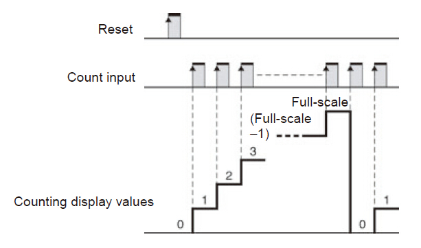
Operating Modes
H7EC Total Counter
Incrementing Operation
(Up)
Nomenclature
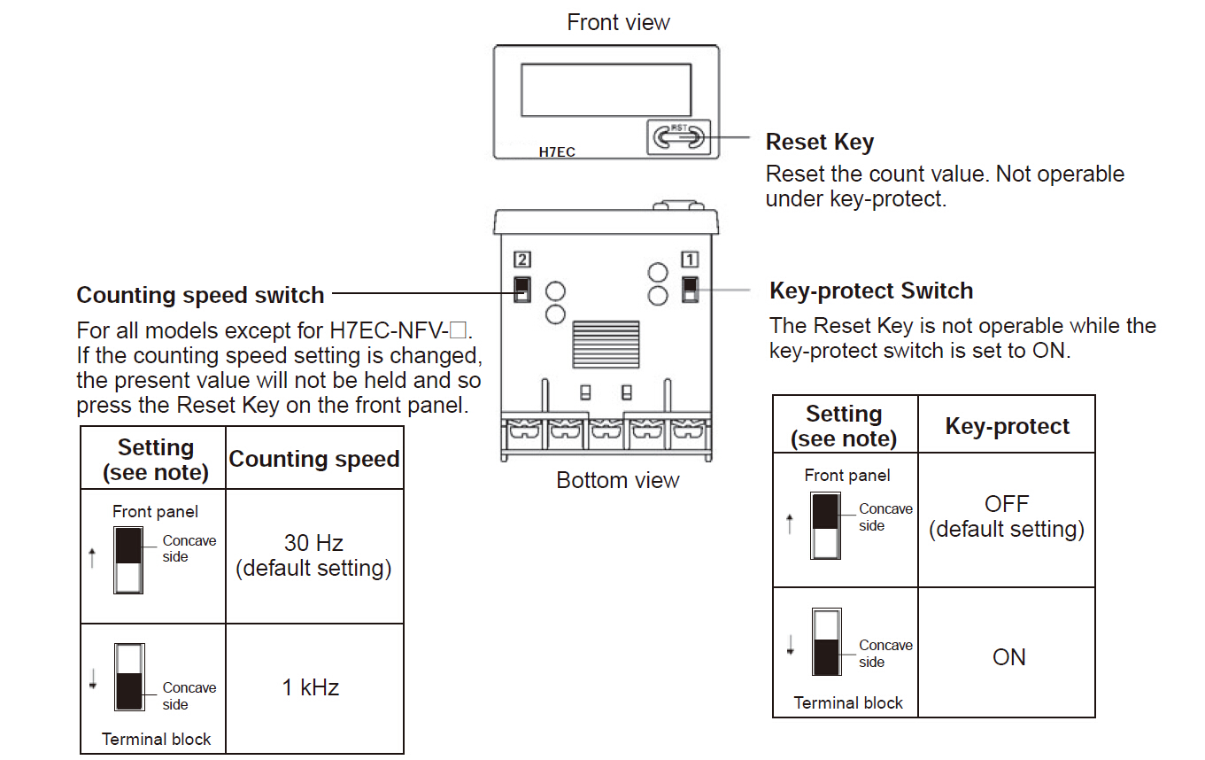
Note:
1. Perform switch setting before mounting to a control panel.
2. If the counting speed setting is changed, the present value will not be held. Press the Reset Key on the front panel.
3. Key protection is used to prohibit operating the Reset Key. The reset input terminals will still be functional.
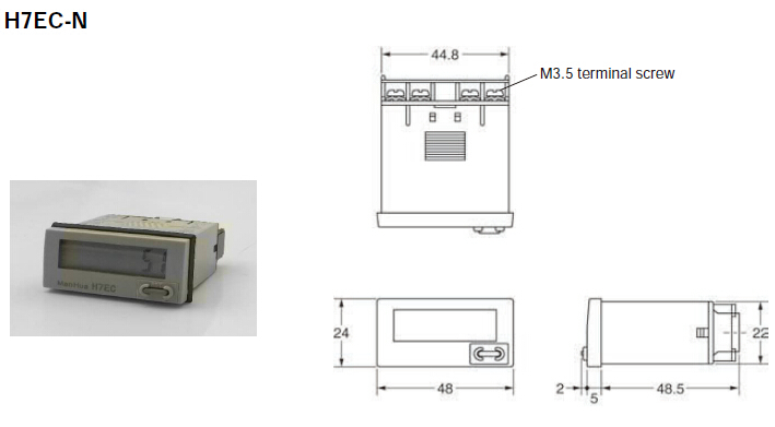
Dimensions
Note: All units are in millimeters unless otherwise indicated.
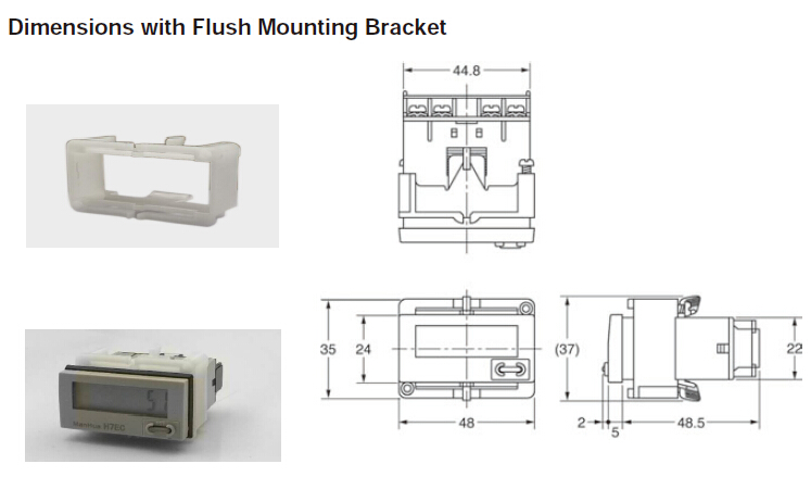
Note: A Compact Flush Mounting Bracket can also be used. Refer to Accessories for details.
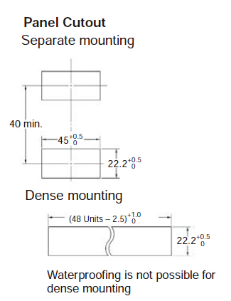
When mounting, insert the Counter into the cutout, insert the adapter from the back and push in the Counter while making the gap between the front panel and the cutout panel as small as possible. Use screws to secure the Counter.
If aterproofing is desired, insert the waterproof packing.
When several Counters are installed, ensure that the ambient temperature will not exceed specifications.
The appropriate thickness of the panel is 1 to 5 mm.